| FM radio from the main stations is transmitted
using some large and very impressive aerials, especially since the BBC
re-engineered all their main stations for mixed polarization. Before the
1980s the main stations tended to use cylindrical slot aerials which,
while technically very impressive, were rather uninteresting to look at
from a distance. The new mixed polarization arrays are much bulkier affairs
which meant that the BBC had to construct new masts at some sites since
the old masts could not carry the additional weight of these larger antennas.
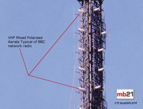
Figure 11
| Figures 11 and 12 provide good
examples... |
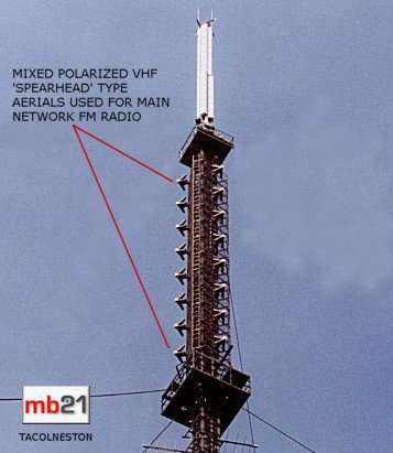
Figure 12 |
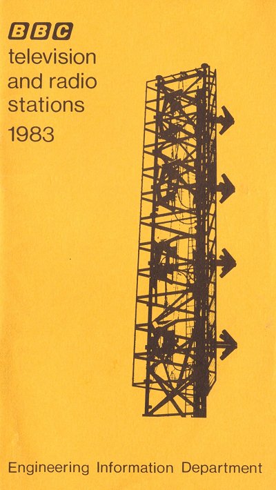
Figure 13 |
... while figure 13 is the cover of a BBC Engineering pocket book providing an
illustration of the new mixed polarization aerials being installed at their main
transmitter at Wrotham in 1983. |
| Many of these aerial systems have been
supplied by ADC, Alan Dick
& Company of Cheltenham.
Figure 14 is a photo of the
Alan Dick Spearhead array.
|

Figure 14 |
Compared with these impressive main stations small local stations and
relays often have very humble aerials. Many domestic hi-fi systems are fed
with a simple three or four element yagi aerial in the loft or on the roof and
figure 15 shows that similar aerials are used at broadcasting stations. In
the example below there are four crossed yagis, two vertical and two horizontal, in a
stacked arrangement providing a highly directional and mixed polarized signal to Wolverhampton and the Black Country.
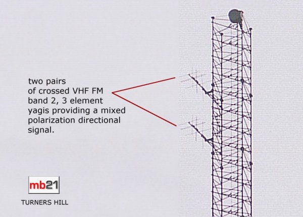
Figure 15
Another type of mixed polarization sometimes used by local stations is 'slant'
polarization and figure 16 provides an example of this type of aerial.
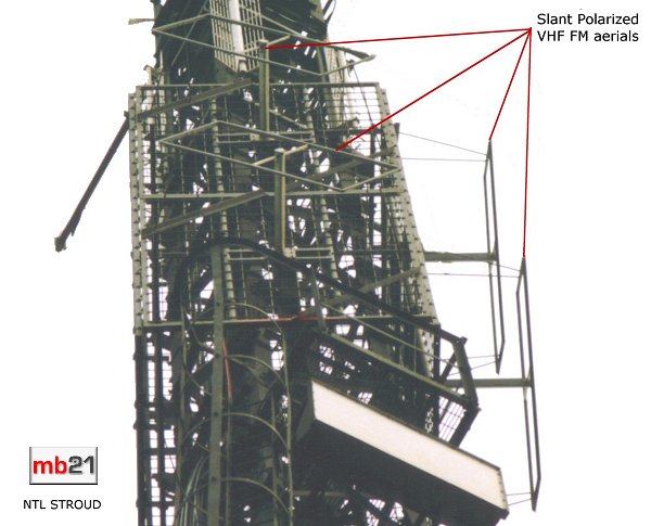
Figure 16
Mixed polarization was introduced by local FM radio in the
1970s to give good reception for listeners both at home with fixed horizontally mounted
roof aerials and with vertically positioned portable radio and car radio aerials. Figure 17 shows an example used by some ILR stations consisting of
two stacked folded vertical dipole aerials and two horizontally mounted folded dipole aerials. The horizontal aerials are bent into a circular shape to
provide a more omni-directional signal in the horizontal plane. The overall radiation pattern will be roughly
omni-directional, but since there is only one array there could be a mast null, in this case reducing the signal to the west.
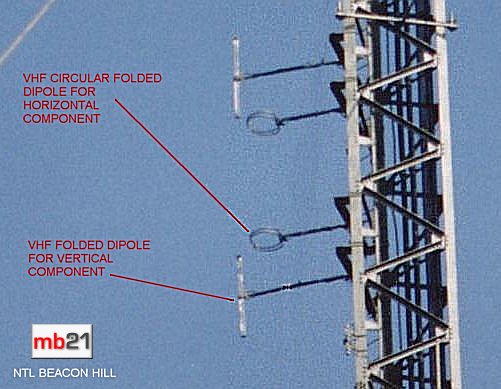
Figure 17
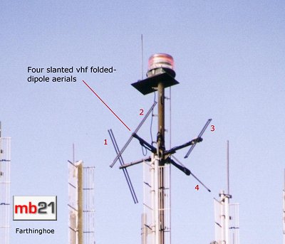 Figures 18
(left) and 19 (below) show two different ILR masts that simply have four or
eight slanted (at 45°) dipoles to provide an omni-directional and mixed polarized signal. Mixed polarization generally involves transmitting an
equal amount of power in both the horizontal and vertical planes, although a
small number of recent ILR stations transmit the horizontal component at 6dB below the vertical (i.e.
one-quarter power). These two examples, however, transmit equal power in both the vertical and horizontal planes. Incidentally
both of these examples are mounted on towers not specially constructed for
local radio broadcasting, but on structures intended originally for other forms
of communication. It's always worth looking out for other masts, such as those used by mobile phone providers, for a new local radio aerial! Figures 18
(left) and 19 (below) show two different ILR masts that simply have four or
eight slanted (at 45°) dipoles to provide an omni-directional and mixed polarized signal. Mixed polarization generally involves transmitting an
equal amount of power in both the horizontal and vertical planes, although a
small number of recent ILR stations transmit the horizontal component at 6dB below the vertical (i.e.
one-quarter power). These two examples, however, transmit equal power in both the vertical and horizontal planes. Incidentally
both of these examples are mounted on towers not specially constructed for
local radio broadcasting, but on structures intended originally for other forms
of communication. It's always worth looking out for other masts, such as those used by mobile phone providers, for a new local radio aerial!
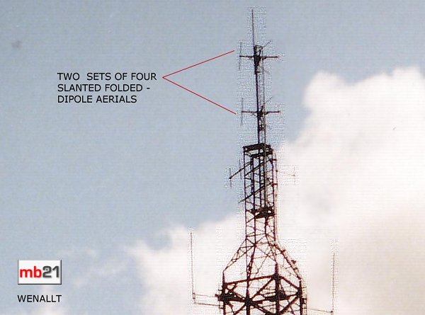
Figure 19
| The next two photographs provide good illustrations of aerials used by BBC
Radio. Figure 20 is a fairly substantial mixed polarization array used by BBC
Radio Hereford and Worcester at their Kidderminster relay.
These are Kathrein panels
which have the advantage that the V & H can be fed separately to ensure equal power split
|
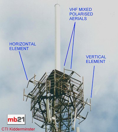
Figure 20 |
| ... while figure 21 shows vertically polarized
'V-90' panels, so called because the dipoles on each panel are in a V shape and the beamwidth is 90 degrees. They're made by Alan Dick |
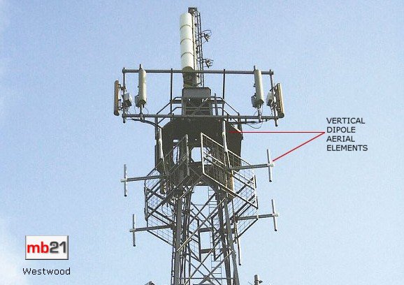
Figure 21
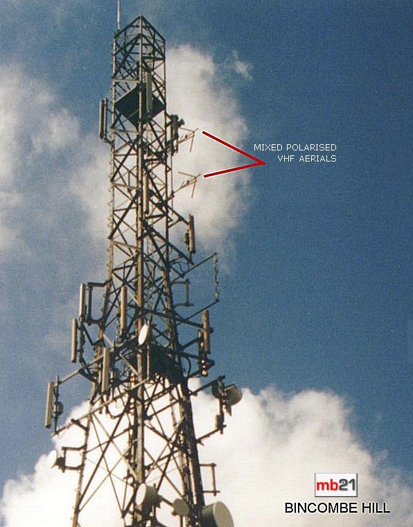
Figure 22
| Figures 22, 22A and 23 illustrate very interesting, and very effective, mixed
polarization aerials used many Independent Radio broadcasters in recent years. These aerials can be seen in use both at lower
power ILR sites and higher power INR1 (Classic FM) sites. Although these
examples show just two stacked antennas, in some instances six can be
used, e.g. ILR and INR at Redruth and ILR at Caradon Hill. Figure 22A
shows a close up.
These are Sira FMC 0-1 dipoles. They are relatively cheap but the don't cover the whole 20MHz of the FM band - a problem for sites with many services but not for local radio.
|
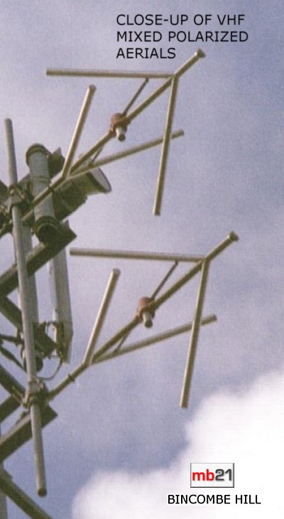
Figure 22A |

Figure 23
| The aerial in figure 24 is the same as in figure 22A, but it has a crossed
reflector element to the rear to provide, in this case, a directional signal to
the south-east, while reducing the signal transmitted to the north and west
where there is another ILR station on an immediately adjacent frequency. |
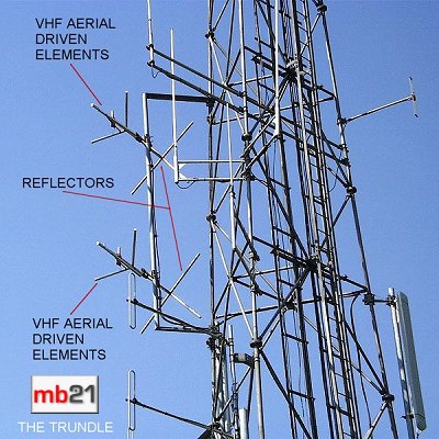
Figure 24 |
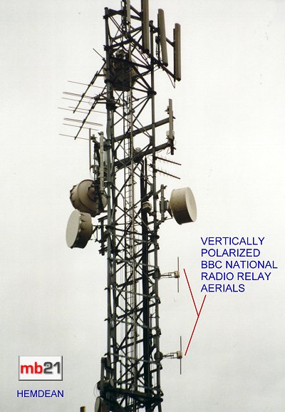
Figure 25 |
In recent years the BBC (CTI) has been busy reinforcing its national radio
signals with a series of new low power relay transmitters. Many of these
small new stations are using vertical polarization rather than full mixed
polarization, this is probably to reduce costs, and figures 25 and 26 illustrate
this. |

Figure 26
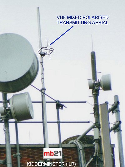
Figure 27 |
To prove that fm radio aerials come in all shapes, figure 27 shows an
unusual, but very simple, mixed polarized aerial nestled amongst some
mobile phone equipment. |
| Finally, figure 28 demonstrates the point that vhf fm broadcasting aerials
can look so much like aerials used by the utilities that they could easily be
overlooked. This is the installation at Acklam Wold for BBC Radio York, which
has also subsequently been used by ILR Minster FM. It is simply two folded
dipoles at the top of the mast. This could easily be mistaken for aerials used
by the fire service perhaps, but if it is possible to judge the length of the
dipole then it may be possible to identify an aerial used for Band II
broadcasting. |
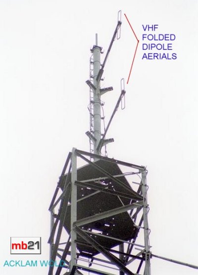
Figure 28 |
|