Currently
all UK DAB transmissions are vertically polarised. There are four reasons
for this:
- Most
receivers are in cars or use “whip” antennas which are
normally set vertical.
- Single
polarisation antennas are simpler and cheaper than mixed polarisation.
- Point
2 also makes it easier to share aperture on the masts used by Band
II VHF-FM antennas (see below).
- There
was no legacy of listeners using horizontally polarised antennas as
with Band II VHF-FM transmissions.
However,
it is interesting to speculate whether, sometime in the future as DAB
receivers become more prevalent, whether mixed polarisation will become
more common. This would match what happened with mobile phones where
initially only vertically polarised antennas were used, but later, as
people expected their handsets to work in any position, mixed polarisation
was added.
| It
is now quite common for DAB antennas to make use of the same aperture
on the mast as the Band II VHF-FM antennas. This means that it
is possible to fit the DAB antenna high on the mast where otherwise
it might have to be much lower down. The downside is that the
when it is necessary to work on either the Band II or DAB antennas,
the other service has to be shutdown too.
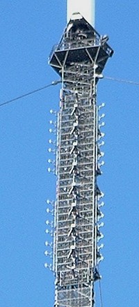
Wenvoe
and Sutton Coldfield are two of the bigger stations that use shared
aperture antennas. The mb21 pictures of the top of the Wenvoe
mast show the extra vertical dipoles in the Band II aperture quite
clearly. In this case, the DAB dipoles project from the “edges”
of the Band II array. |
 |
 |
In
other cases, the DAB dipoles are mounted to the face of the screening
mesh behind the Band II antenna elements.
Typically,
there are 2 tiers of dipoles for each Band II dipole. This give
the possibility of the DAB antenna being higher gain than the
Band II (if the whole aperture is used), or of not fully filling
the Band II aperture if the extra gain (and complexity) is not
needed.
Sheffield
uses a shared aperture antenna of this type. The mb21 picture
of the Band II antenna clearly shows the 4 – tier DAB antenna
using the same screen as the 2 tier Band II. Each Band II dipole
has 4 DAB dipoles sharing its reflector screen.
On
the same picture, the vertical dipoles off the corners of the
antenna array are parasitic (i.e. unpowered) Band II radiators
to improve the vertically polarised radiation pattern from the
antenna. |
|


