
 |
UK Broadcast Transmission |
        |
|
    |
|


|
|
|
|
||||||||
|
|||||||||||
HOW TO RECOGNISE MORE TYPES OF BROADCASTING AERIALS FROM A QUITE A LONG WAY AWAY
By Roger Piper
Broadcast Aerials
|
|
|
|
Some of the aerials previously described by Mike Smith are also to be found in use at lower power tx sites. Others, as below, are only used at lower power tx sites.
|
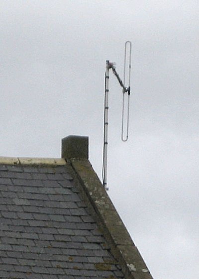 |
UHF Television Low power television tx sites use the aerials previously described. VHF FM Radio and VHF DAB Radio The aerials designed for use in the radio telecommunications industry (Private Business Radio (PBR) etc.) are generally rated for a power of 200 Watts so offer a cost effective means of transmitting low power FM band II and DAB band III signals. Commonly used is the folded dipole, often referred to simply as a dipole, seen here at Stonehaven. |
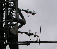 |
Dipoles may be paired to give a directional effect, as here at Lark Stoke. If it’s possible to estimate a dipole’s length its frequency can be calculated from l = 150/f where l is length in metres and f is frequency in MHz, then allowing for a reduction in length of about 5%. For reference, if there’s a nearby TETRA dipole stack the length of each dipole will be approximately 300mm and the overall length of the vertical support tube is likely to be 2500mm. Standard aluminium scaffold pole is widely used for aerial supports and is 48.5mm diameter. |
|
Incidentally, the term folded dipole is, perhaps, a bit of a misnomer as it implies that an ordinary dipole aerial, as seen at two probable pirate installations later, is, literally, folded up, reducing its length. In fact the overall length of a folded dipole is to all intents and purposes the same as that of an ordinary dipole aerial consisting just of two rods or tubes. Beware, though, of optical illusions. This band II FM dipole pair at Amersham is deliberately mounted to be sloping with the top away from the camera and that, together with the camera angle, makes the dipoles appear only about half of their real length. If viewed exactly broadside the slant of the dipoles would not be obvious. |
 |
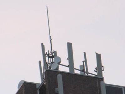 |
If the aerial is hidden inside a plastic tube it’s impossible to tell from a distance what’s inside. A given length of tube may contain a single element half wavelength long, or it may contain several elements end to end, in line (collinear), for a much higher frequency. They are used at some low power DAB sites where they are usually given a prominent position, as here at Staines where the aerial is mounted above a tier of mobile phone aerials. |
| They are also used at Community Radio FM transmitter sites, such as at Eliot College. | 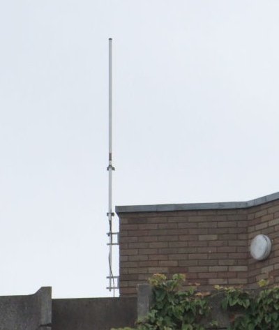 |
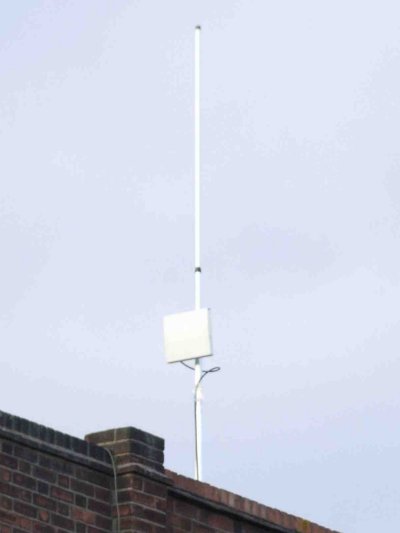 |
Many Community Radio operators use a radio link to transfer the studio’s output to the tx site, known as an STL (Studio to Transmitter Link). Some use frequencies close to 1.5GHz and the commonly used receive aerial is enclosed in a slim white plastic fronted rectangular box. Others use band I frequencies and the commonly used receive aerials look similar to an old 405 line BBC tv aerial mounted horizontally. STL receive aerials are often mounted lower down the same pole which supports the tx aerial, as here at Harlesden (1.5GHz STL). |
| Band I has been used for the STL at Harold Hill. | 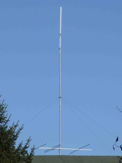 |
|
|
Many of the FM pirate radio stations also use band I STLs, though. The general style of this installation suggests it’s a pirate radio one, and it uses a vertical dipole at the top for tx and a horizontal dipole off the top of the scaffold framework for receiving the STL. |
| Sometimes it’s more difficult to identify pirate installations. From a distance these two stacked dipoles look legitimate, but close inspection suggests otherwise. A professional installer is unlikely to have used such lightweight cable to connect the two individual aerials... | 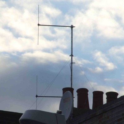 |
| ... That, and the way they’ve been joined to the main cable, suggests it’s a pirate installation. |  |
 |
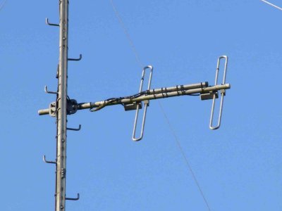
By way of comparison the two dipoles at this CR site use larger diameter cable, and a commercial cable harness to combine the two aerials. The three way cable junction is protected by a plastic box (blue arrow) and the joints between the aerial ‘tails’ and the harness, and between the harness and the main downlead, use connectors protected by tape (red arrows).
Low band (68-87MHz) PBR installations often use a pair of aerials looking similar to this but they usually have separate cables with one aerial used for transmit and the other for receive. |
|
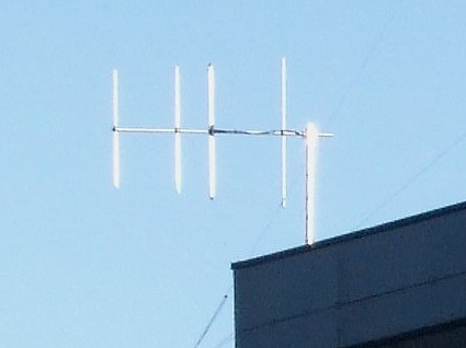
Receiving aerials Mike Smith has mentioned that log periodic aerials (LPA’s), commonly referred to simply as logs, are often used at tv relays for both reception and transmission. A somewhat larger version is often used as a receive aerial at band II FM radio relay sites, as here at Membury. |
 |
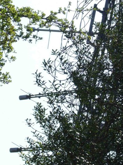 |
At Guildford the pair of horizontal logs, just visible through the trees, is aimed at Wrotham, and the vertical log is aimed at Crystal Palace to give an alternative feed source. |
|
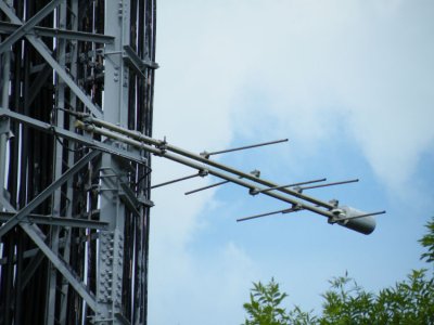
Conventional yagi beam aerials are used to receive the incoming signal at some sites, such as here at Amersham. |
 |
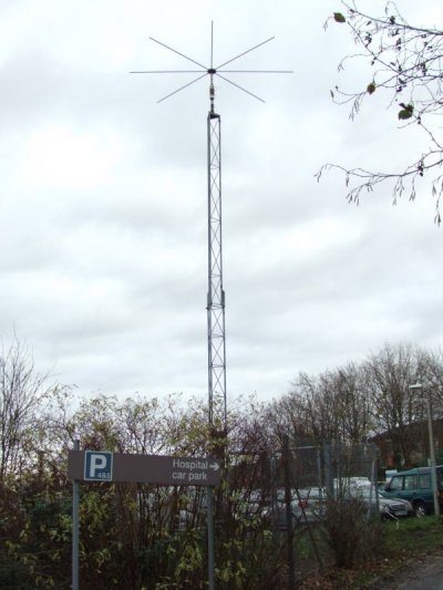 |
MF – AM Radio Low power MF tx installations are not common, but normally use a short vertical radiator, sometimes referred to as a monopole, with a number of radial metal rods at the top. This one at Oldham Royal Infirmary uses a slim lattice mast. |
| This installation at Luton and Dunstable Hospital uses a white tubular pole. |  |
