
 |
UK Broadcast Transmission |
        |
|
    |
|


|
|
|
|
||||||||
|
|||||||||||
THE TRANSMISSION GALLERY
CROYDON
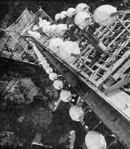 This view from the top of the tower shows clearly the offsetting of dipole pairs on the south side of the tower |
I.T.A.'s NEW LONDON TOWER
From an article first published in the January 1963 issue of Wireless World The aerial tower from which the first London transmissions of Independent Television Authority were made in 1955 is a 200-ft. lattice structure at Beulah Hill, Croydon. It carried a straightforward omnidirectional Band III aerial, had an effective radiated power of 120 kW, uniformly distributed in the horizontal plane, and has served its purpose well in establishing the ITA service over London and the neighbouring countries. |
Experience has shown the need to extend the service area substantially to the north and north-west and to reduce it in other directions-notably to the south-west, where interference with the ITA station working on the same frequency at Stockland Hill, Devonshire, would otherwise be serious, and to the east, south-east and south to minimize interference with Continental stations. Electrical Characteristics To meet these needs a new aerial was commissioned from EMI Electronics Ltd. with BIC Construction Ltd. acting as sub-contractors. |
|||||||||||||||
|
The specification to be met was as follows: The 80-ft. top section was assembled at Hayes, using the foundation of steelwork forming part of the mast structure. This top section is parallel and square and carries eight stacked "rings" of dipoles mounted on reflector panels a wavelength in length at the Band III mid frequency. Twin stacked pairs of dipoles are mounted on the north- and south-facing panels, but the east and west panels carry only single stacked pairs. The position and phasing of the dipoles in a single ring were first adjusted to give the salient features of the required radiation polar diagram. |
||||||||||||||
This inevitably contains a number of nulls due to interaction between dipoles, and in the complete assembly the technique known in the vernacular as "null smudging" is applied, the dipoles in adjacent rings being slightly offset to fill in the gaps in the required radiation pattern. The vertical as well as the horizontal pattern must be treated in this way. The main beam is deflected downwards only 0.5° from the horizontal but there are a number of weaker downward-firing lobes, which, when blended with about 20% of "fill-in," give ample signal strength for viewers in the vicinity of the station. To verify calculations and make final adjustments, tests were made on a revolving test mast in open country near the EMI works using the transmitting aerial as a receiver for signals from a low-powered transmitter about half a mile away. |
|||||||||||||||
Tower Structure Meanwhile, work had been proceeding on the tower base. The Site area was restricted and the base width(60 ft.) is only half that of the nearby B.B.C. television tower at Crystal Palace. To prevent variation of the field strength due to tilting of the horizontal main beam the specification nevertheless called for a maximum deflection of not more than 1 degree of arc (10 inches at the top of the tower) for a wind speed at the top of 100 mph. The difficulty of the designers was further increased by the stipulation of the aerial manufacturer that the width of the sides of the top section could not exceed 5 ft. In making these calculations account had to be taken of the possibility of further extensions of height by, for example, UHF aerials on candelabra masts at the corners of the top platform. Bore holes 40 ft. deep revealed clay foundations easily capable of bearing the deadweight of the tower (250 tons) and of the concrete foundations (1,040 tons). Each leg of the tower is supported on a block 20 ft. square and buried 15.5 ft. deep to help in resisting by the principle of the "friction wedge" of the overlying earth the uplift force due to wind pressure. High-tensile steel members of cruciform section were chosen to give minimum wind-age. Accurate cutting and drilling of the members is essential and was carried out at the Hereford works of Painter Bros. Ltd. (a member of the BICC. group) on full-scale "loft" drawings, after the manner of shipbuilding. Each member was hot-dip galvanized before assembly, and it is not expected that any painting or other maintenance will be necessary for 4 or 5 years. |
|
A box girder runs up the centre of the tower and supports the coaxial feeders. There are two of these supplying separate 40-ft. sections of the aerial to give continuity of operation at reduced power in the event of breakdown. The feeders are three-eighths inch diameter semi-flexible aluminium outer tubes with coaxial centre conductors spaced by laminated polystyrene helical tapes. The feeders were supplied on 12 ft diameter drums from which they were winched up from the base of the tower into position in less than 4 hours. Dried air is pumped up the feeders to all junction boxes and the 2.5 inch diameter dipoles, the latter being protected externally from the effects of snow and ice by pods of plastic material extending 30% of the length from the centre feed points. Having completed this project the ITA is now in a position, as far as the "hardware" is concerned, to meet any future expansion of its services in the London area which it may be called upon to make by the Government. It also has the satisfaction of knowing that the design has the approval of the Royal Fine Arts Commission. |
|
Croydon Band III coverage area map
Croydon index | Crystal Palace
|

