
 |
UK Broadcast Transmission |
        |
|
    |
|


|
|
|
|
||||||||
|
|||||||||||
CONSTRUCTING STAYED MASTS
By Brierly Hill
First, some definitions so we can all get it right:
There seem to be two main techniques for building tall masts: what may be called the 'traditional' system which was used for example to build the original mast at Sutton Coldfield, and the 'modern' one, which was used to build its replacement. All other methods seem to be an adaptation of one of these processes.
Irrespective of the method, mast erection commences with preparation of the site. A large hole is dug at the appointed spot, and filled with concrete - many tons of it - forming a support base to spread the considerable load. At the same time, holes are dug and filled for the stay anchor-blocks. Like the iceberg, the greater part of these blocks is invisible, underground.
 When the mast base block has cured sufficiently, a fixed mast base plate is attached to it. This photo [right] gives a reasonable picture of a mast bottom-end, though details vary between masts: some use a fixed raised plinth system instead of a surface-mounting plate. The point of contact of the mast with the base-plate is in fact a ball-joint: this allows the mast to 'sway' slightly without causing excessive stresses in the lower mast members. The lower plate has a semicircular recess machined in its top surface, and the upper plate a similar one in its lower. The two plates are located together with a steel ball, which fits into the recesses. Some later designs dispense with the ball, and use a machined convex spherical surface on the top of a fixed plinth, with a matching machined concave surface in the base of the first mast section: but the principle is the same.
The tapered lowest section of the actual mast usually arrives pre-assembled on a lorry. A hearty dollop of waterproof grease is loaded into the lower locating hole, the locating ball popped in and greased over, and the first mast section is craned into position and lowered onto the ball, and then held vertically in place by temporary stays.
Actual erection of the mast now proceeds....
Let us look at the 'traditional' method first.
Here, the mast is extended in sections, and each section is constructed of separate panels, one for each side of the mast. These separate panels arrive on site ready assembled, and are hoisted into position separately and bolted into the section at altitude. This is a lengthy and hazardous procedure. Such panels were usually constructed of steel angle or channel, constructed in a jig at the works. Before assembly all sections would usually have been hot-dip galvanised.
To raise the panels into position, a contraption called a 'flying jib' was used. This was a long pole sitting inside the top of the mast structure, with rather more than half of its length sticking out of the mast top and held in place at its centre and bottom by adjustable strops, which enabled the position of the jib to be altered. The top of the jib had a pulley, with a long cable running from a ground winch, up to the pulley and then back to the ground. The new section would then be hauled to the top of the mast, positionally controlled by tail' cables trailing from the bottom of the panel to the ground. These would be tensioned so that the panel didn't swing into the mast or strike the stays. On arrival at the top the panel would be positioned by shifting the flying jib, and then bolted into position with fishplates. After a section has been completed, the flying jib then had to be hoisted up inside the mast into its new position at the mast top, ready for the next section.
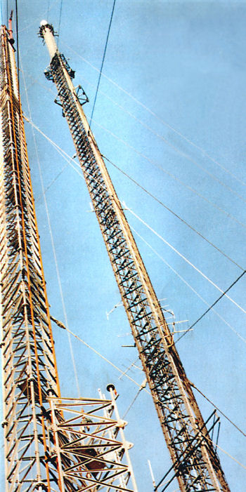 |
For the 'modern' method of construction, take a look at this photo of Wenvoe [left] - this picture is of the Wenvoe mast, and shows the method well. Notice that on the new mast (the left-hand one) there appear to be two orange strips running up the mast on the right-hand face. These are actually temporary rails, up which a carriage runs. The carriage can be seen at the top of the mast, and carries a cylindrical red pole with a jib mounted on its top. This jib can swivel through 180 degrees in a horizontal plane. The pole overhangs the mast top by rather more than a new mast section, although it doesn't look it from the ground. Note the cable coming down from the jib to the new mast section on the ground in front of the mast. This cable will haul the completed section to the top of the mast, travelling along the guide rails and located by temporary runners. Unlike the 'traditional' method, mast sections arrive on site fully assembled and ready to hoist into place. Such sections are usually constructed of tubular steel rather than angle, and are assembled in a jig at the works by welding rather than bolting. Sections here are usually joined by circular flanges rather than fishplates. After weld inspection, the section is then rust proofed either by galvanising or some suitable paint-type treatment, and despatched to site. The new section is hauled to the top of the mast, swivelled round so as to lie above the last erected section, and dropped onto the previous section and bolted in place via the round flanges on the mast leg ends. The new section already contains temporarily assembled rails as an extension of the existing ones, and once the new section is secure the jib carriage will be moved up onto it. The next section will already have been prepared on the ground and be waiting its turn. When the mast is complete, the carriage is run back to ground and the temporary rails removed. It can be seen that the 'modern' method drastically reduces the amount of haulage necessary, and also the amount of construction work to be undertaken at height. |
Irrespective of the method used, the following steps apply to all.
After a new section has been added, it 'overhangs' the mast top so new temporary stays are attached to its top, to stabilise it. There are usually two sets of temporary stays, which 'somersault' each other up the mast, with the permanent stays being added in their final locations as their anchorages become available.
All the time this is going on, there are two chaps with theodolites out in the field, checking that the thing is vertical - any errors being taken out by adjusting the stay tensions. Stay tensions are critical - if not correctly balanced, the structure will not be vertical (and they aim to get it so within a couple of inches for an 800 foot mast). If the tensions are too great, the structure may be damaged - some have been, in the past. If too slack, the stability of the structure is impaired. Tensions would be set up with a device rather resembling an enormous spring-balance, clamped to the stay-block and taking the strain of the stay off the anchorage. Unlike the average spring-balance calibrated in pounds, these were calibrated in tons. To give some idea: the weight of the original Sutton Coldfield mast was given as 160 tons, but the downward force on the ball-joint at the bottom was 300 tons. The difference was entirely due to the downward component of the total stay tension. You may think that 300 tons is rather a lot to put on a 3-inch diameter steel ball, but when the ball was removed after nearly 40 years service, it was in perfect condition.
Later adaptations of the modern' principle were used in the construction of the temporary replacement mast at Peterborough, 2005. In this photo [right] the lifting pole doesn't seem to be running on a track, but is mounted on frameworks that appear to be attached to the last erected section. The weight of the pole and frames seems to be taken by two flexible straps tied off to the mast legs above. In this case, the lifting jib has been used to hoist an inspection cradle rather than a new mast section. |
 |
| In the photo [below] there seems to be quite a lot of overhanging mast section that has not been stayed: the top set of stays visible is temporary, whereas the set below are permanent. On completion of the mast, the lifting structure would have to be dismantled and lowered piecemeal, since it would not pass the stay anchorages. |
 |
|
 Tubular masts, like Waltham and Mendip Waltham, are a slightly different proposition. Here, the structural mast member is a single steel tube, fixed to a rigid plinth built on the concrete base block - there is no ball joint, tubular masts are much more flexible than lattice ones, the entire structure is designed to flex safely in the wind. This photo of Waltham shows a good view of a base plinth.
Erection of tubular masts has to use a version of the 'traditional' flying-jib method to raise the sections into position. The sections arrive as curved-steel segments, usually with any fixing attachments for stays, internal ladders, feeder trays, lift structures etc. already attached. The section is raised into position, and held there using an attachment jig, which critically positions the segment relative to those previously erected. The new segment is then welded into position by presumably highly-paid operatives (since they are both welders, and working in a hazardous location). Other than these differences, construction proceeds much as for a lattice mast. On completion, the welded areas have to be painted, since welding would have destroyed any previously-applied treatment.
With the mast completed, vertically true and on its permanent stays, you still haven't finished of course. There are still the aerials to install, miles of cabling and feeders, permanent mast lighting (you may have had to have temporary lights on it during the construction phase), ladders, microwave dishes, you name it...
The Trouble with Tubular Masts | Features index
|