 |
UK Broadcast Transmission |
        |
|
    |
|


|
|
|
|
||||||||
|
|||||||||||
THE TRANSMISSION GALLERY
TALES FROM A COLD FIELD
Being fairy-stories told to the author as a young engineer
© Ray Cooper, 2005 (2nd revised edition, Jan 2006)
Appendix B: The original Band I TV Aerials It is interesting to remember that the Band I aerial system was designed a mere twelve years after the pioneering Alexandra Palace (AP) installation (an intervening World War caused some inconvenience, though it did speed technical progress). Despite this short period, in design terms the two systems were like chalk and cheese.
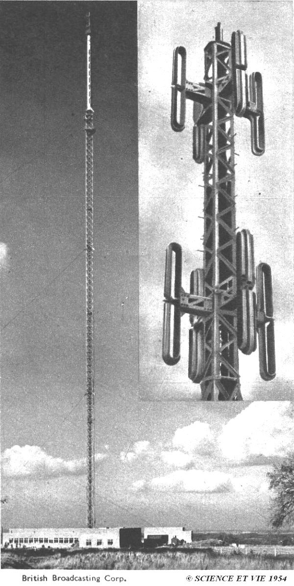
Now I have seen many historical photos of the AP tower, but I can assure you I have never seen the aerials - they are usually invisible in photographs, consisting of vertical wire-cage elements suspended between the ends of the horizontal support spars, which are the visible bits that most people think are the actual aerials themselves. There were also driven wire reflector elements between them and the mast structure. To modern eyes it was a distinctly odd arrangement, though it worked well enough. The Sutton Coldfield arrangement amounted to two tiers of four dipoles arranged around a stub lattice mast cantilevered above the main mast. (The 'Transmission Gallery' page for Sutton Coldfield shows a photo giving a good idea of the original layout). The individual dipoles were of folded construction, centre driven, and contained box channels which improved the bandwidth, stiffened the structure and contained many kilowatts worth of AC mains heating, to try and keep icing at bay during the winter months. This was only partially successful: RF got into the mains wiring and regularly burnt it out. For most of their life, the aerials just had to put up with the ice.
Unlike the AP arrangement, both tiers were fed with combined sound and vision signals, thus doubling the aerial gain 'at a stroke'. Compared with all other known sites, the sound-vision combiner was, most unusually, originally mounted at the top of the mast, fed with sound and vision signals via separate feeders. The design reason for doing this has always eluded me: perhaps it was felt that matching the long feeders for both signals simultaneously might prove difficult. In the event, the combiner itself proved less than trouble-free, and its location from a maintenance standpoint was a total disaster. In later years, when the building was extended (for the FM radio expansion) the combiner was moved down to ground level, to universal relief. When the new UHF aerials were installed, the Band I arrays had to change, of course. The old cantilever extension was cut off, and the top of the FM cylinder extended upwards somewhat. On the outside of this extension, the new Band I aerials were mounted. They consisted of two tiers of six dipoles supported near the ends of horizontal support members. There was a little more to these supports than met the eye: in engineering terms, the whole assembly was 'a balanced dipole on a tapped stub', and the stubs (the support members in disguise) actually acted as baluns which converted the unbalanced coaxial feeders to balanced outputs, and also provided a degree of impedance matching across the channel. Another odd aspect was the proximity of the top stays to the top tier of dipoles. This caused some distortion of the radiation pattern (it actually introduced three partial nulls at 120 degree intervals). In order to overcome this, three 'scatter elements' were installed in the top tier - these were simply parasitic rods of about one-half wavelength, which made the top tier think that there were actually six sets of stays rather than three. The upshot was that there were now six nulls in the horizontal radiation pattern, but each of very considerably less depth than formerly. |
|
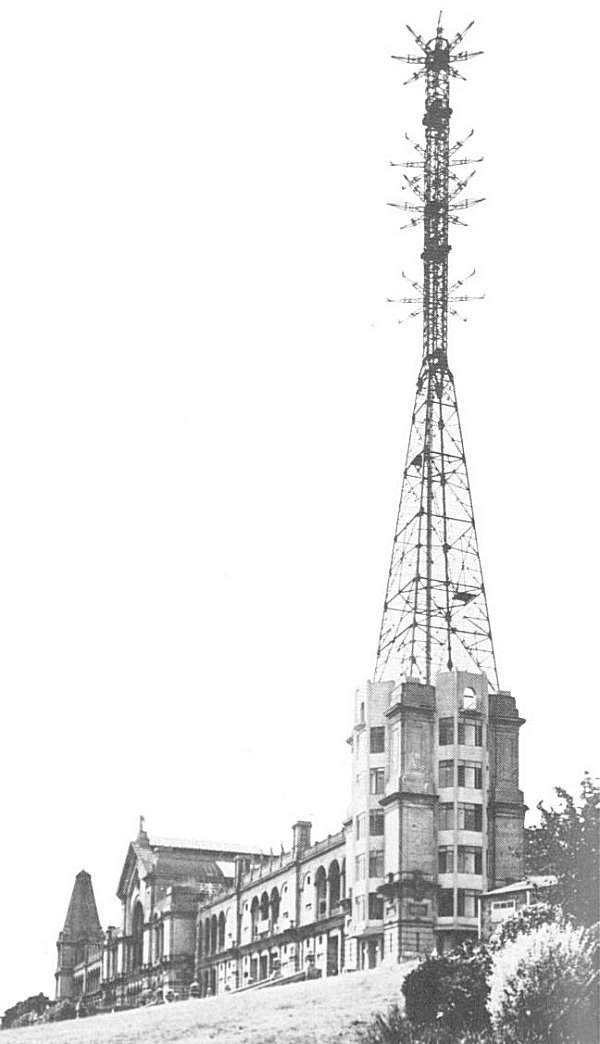 To digress a little: the original AP aerial consisted of two tiers, the top one radiating vision signals, the lower one sound. A distinct feeder fed each tier, and at no time did the sound and vision signals come together.