 |
UK Broadcast Transmission |
        |
|
    |
|


|
|
|
|
||||||||
|
|||||||||||
THE TRANSMISSION GALLERY
TALES FROM A COLD FIELD
Being fairy-stories told to the author as a young engineer
© Ray Cooper, 2005 (2nd revised edition, Jan 2006)
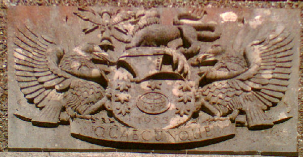
Appendix A: The Half-Crown Tour of Sutton Coldfield, 1950 style The station was built right on the edge of the Sutton Coldfield town conurbation, overlooking green fields to the north. As originally constructed, the buildings were rather smaller than the present spread of premises, and consisted largely of two wings set at right-angles in an 'L' formation: one was the transmitter hall proper, and the other the administrative block, canteen, kitchen and some store-rooms. Outside, detached from the main block, was a large garage and electricity substation. Whilst we're still outside, just look up . Outside is the main mast: you can't miss it. It was a 750ft. stayed lattice mast, built by BICC, with the Band I TV aerials at the very top. See the appendix 'Original Band I TV Aerials' for more detail on these. All four of the original post-AP main stations used much the same design of mast, barring slight variations in height and constructional weight, to suit the prevailing geographic needs. The other feature worthy of notice on the mast is the presence of the FM slot aerials, in position and ready for service, some eight years before they were to be needed. Somebody was evidently thinking well ahead. As built, the mast incorporated its own lift, winch-driven. This lasted until the arrival of UHF broadcasting, when it was found that there was insufficient room for both the lift and the new feeders that were needed - so the lift had to go. Using the lift it took about five minutes to ascend: on foot, using the adjacent ladders, more like half an hour if you were fit. Between 1949 and about 1968 there was also a 'baby' 150ft. mast adjacent. See Appendix C for its further history. In we go. . at the main entrance, located in the angle of the 'L'. Above the double-swing doors was the BBC coat-of-arms. Unusually, the motto beneath it was not the usual 'Nation Shall Speak Peace Unto Nation' so often seen: instead, the single word:
Quaecunque Now I am no Latin scholar, neither were most of the other staff, so I can't give you the literal meaning of this. However, I always believed that a general translation would be 'whatsoever' or perhaps 'whomsoever'. Most people felt that a translation 'What the Hell' would be nearer the mark. This was certainly the motto by which most of the inmates lived. Everybody into the Band I Transmitter Hall, now.This was quite a sizeable hall, long and thin. In the old AP installation, the control desk for the transmitters was sited in the transmitter hall, a location much too noisy for quality monitoring of sound output. Sutton had the benefit of a separate control room, with elegant curved glass windows looking out into the transmitter hall. As the shift TA sat in his position of power at the desk, he could see the Sound transmitter out of the left-hand window, the Vision transmitter through the right-hand one. In front of him would be a number of picture monitors; above these, mounted on the brick wall between the windows, the transmitter Mimic Panels. These were delightful affairs that told him, in coloured lights, the state of just about every important item in the transmitters: individual power supplies, overloads, over-temperature warnings, water and airflow rates - everything a lad could want to know. On the top of all, there was a big lamp, which said simply - 'ON' - a nice touch, I always thought. The vision mimic panel itself must have had in excess of a hundred bulbs - all post-office wedge fit types - and replacing just the faulty ones was quite a maintenance effort in itself. Outside in the main hall, were the two main transmitters - sound and vision. In typical BBC parlance these were given identifiers: the sound transmitter was known as T1, the vision T2. This was in line with the then-current BBC attitude that the sound part of the programme was more important than the pictures. T1 - the Sound transmitter, was a conventional affair. Basically it was a standard Marconi short-wave transmitter of the period, wound up in frequency to Band I, and with the modulator circuits tweaked for the extra sound bandwidth needed for TV sound. In those days television sound was of the best quality available on the airwaves. The transmitter ran at about 12.5kW output power. Being a standard unit, it gave little trouble. T2 - the Vision transmitter, was very much otherwise. A strange manufacturing hybrid, it was officially described as a "Marconi-EMI-MetroVick". What this meant in practice was that the modulator sections had been made by EMI: most of the RF side by Marconi: and all of the power supplies (which were very extensive, and occupied another room) by Metropolitan Vickers. Each company had their own different way of doing things, which helped keep the staff on their toes. See Appendix D for details of the physical layout and circuitry involved. |
Time to meet some of the staff >
|